I'm not a gamer, I run flight sims from time to time, but from what I have read Grendel has tweaked his firmware to poll the joystick twice as fast as Windows does normally. Faster would be better, right? How much better I have no idea. I would assume it will reduce lag, but there are other factors at play that affect lag also... As I said, they will both work. Try them and see which one you prefer. Choices are a good thing.kyanite286 wrote:Thank you for the clarification. I would like to use the FFB effects. WHat do you mean it is not optimized for gaming? How will it be affected. I really only use it in descent freespace and some other space sims.
Reverse Engineering the Force Feedback Pro
Re: Reverse Engineering the Force Feedback Pro
=================
More info is on MY SITE.
More info is on MY SITE.
Re: Reverse Engineering the Force Feedback Pro
sparx... If you look on page 4 of this topic you will see that "nosuchuser" tried what you are trying now and it looks like he had similar symptoms. He states that the LUFA device would show up in Device Manager and then disappear, but never show up in control panel. Unfortunately I don't know how his attempts ended up. I suppose that he either got it to work or gave up...since he never posted again that I can see. :/
=================
More info is on MY SITE.
More info is on MY SITE.

Re: Reverse Engineering the Force Feedback Pro
Many thanks Scott, that's plenty of trails for me to follow now.
I'll let you know when I made some progress. Also, I'll have a go with the Arduino Leonardo on a different dev board to rule out a faulty Arduini Micro (had it for a while and it's been doing lots of other things).
Happy new year everyone.
John.
I'll let you know when I made some progress. Also, I'll have a go with the Arduino Leonardo on a different dev board to rule out a faulty Arduini Micro (had it for a while and it's been doing lots of other things).
Happy new year everyone.
John.
Re: Reverse Engineering the Force Feedback Pro
I can now report a partial success. The issue was a LUFA USB2Serial .inf file that had the same USB ID (used the Arduino micro in a previous project). 
However, although I now get a device "LUFA Joystick wFFB" under "Other Devices", the Joystick gets recognized and is listed in joy.cpl but with only half the buttons and axis working as I now have 16 buttons listed (button 3, 5 and 8 are permanently ON) and the Coolie-Hat only works up/down while sidesway (L/R) won't work at all. Buttons A and D are dead. Also dead is the long button left of the Coolie-Hat.
Not sure what the issue is now, especially as the Arduino Micro seems to be doing the job. I'll have a look at the software protocol which may provide further hints. I will also heck the joystick to make sure there are no dead contacts. However the joystick was always well kept and looks like mint from the outside but who knows how it looks on the inside as I haven't used it for years.
John.
Re: Reverse Engineering the Force Feedback Pro
Glad to hear you're making progress.sparx wrote:I can now report a partial success. The issue was a LUFA USB2Serial .inf file that had the same USB ID (used the Arduino micro in a previous project).
However, although I now get a device "LUFA Joystick wFFB" under "Other Devices", the Joystick gets recognized and is listed in joy.cpl but with only half the buttons and axis working as I now have 16 buttons listed (button 3, 5 and 8 are permanently ON) and the Coolie-Hat only works up/down while sidesway (L/R) won't work at all. Buttons A and D are dead. Also dead is the long button left of the Coolie-Hat.
Not sure what the issue is now, especially as the Arduino Micro seems to be doing the job. I'll have a look at the software protocol which may provide further hints. I will also heck the joystick to make sure there are no dead contacts. However the joystick was always well kept and looks like mint from the outside but who knows how it looks on the inside as I haven't used it for years.
John.
I just hooked mine up again to double check things. You will have 6 axis displays and 16 buttons as well as the hat shown in the control panel. Of these, only the Z rotation and throttle will be active and buttons 1-9 along with the 8 position hat.
From my experience with my stick and other posts here, if your stick shows some buttons working and not others it is almost always the joystick at fault. The stick is digital so all the button and axis info share the same pins in the db-15. I had several buttons not working on mine when I pulled it out and hooked it up. Mine was stored pretty well too. Not climate controlled in a plastic bag, but it was room temp in a dry closet.
(for the benefit of others) First, identify which buttons are not working. Buttons from 1-9 in order are as follows:
1-trigger
2-left button on top of stick
3-top right on stick
4- bottom right on stick
5-A on base
6-B " "
7-C " "
8-D " "
9-shift " "
Try cleaning the button switches. I had pretty good luck using a drop of 91% (DON'T use normal 70% as it contains too much water) rubbing alcohol on the switch and then work it in and out as well as circular as best you can to get the contact surfaces inside to rub a bit. Add a drop of alcohol from time to time to keep it moist while you work with it. After a few minutes of that, spray it with canned air to dry it. (it won't be dry inside) Move on to the next faulty button and repeat. You can check your progress on a switch with a VOM meter, using a good switch as an example of which pins should make connection on a press. If you don't have a VOM then I'd let it sit open to dry completely for a day or 2 and then test it again. Actually I doubt if a bit of alcohol inside the switch will cause a problem but not being 100% certain, I'd err on the side of safety. Let it dry. If any buttons are still not working (hopefully most of them were revived) then make note of them and repeat. The only other option is to find new switches and replace the faulty ones. I managed to get all mine working. One is still a bit flakey if I don't press it "with authority" but I can live with it. If I cleaned it one more time it might be fine but...eh...other things to do.
I'm not sure if the hat uses 4 or 8 switches.It feels like 4. I don't think I had to tear the handle apart (it's been a while). If it uses 2 switch presses simultaneously to indicate a corner, then having your left and right switches faulty will eliminate any chance of a corner lighting for you in the control panel. Fixing left and right will automatically give you the 4 corners.
Good luck. Once you have it all going, I hope you'll post a schematic of the connections used on the Arduino for the benefit of others, or if nothing else, a text listing of which pin on the Arduino matches which pin on the Teensy.
Scott
=================
More info is on MY SITE.
More info is on MY SITE.
Re: Reverse Engineering the Force Feedback Pro
How to wire up an Arduino Micro without any modification to the software used by the Teensy++ and Teensy 2.0 board.
Let's start with a schematic for the original Arduino Micro: http://arduino.cc/en/uploads/Main/ardui ... ematic.pdf
For those who plan on using an Arduino Leonard (also based on the ATmega32u4 MCU), the Leonard board has the pin PB0 hard wired to an LED and you will have to de-solder the tiny LED in order to bring out that specific pin or change the software to use a different pin (which will require to visit the ATmega32u4 manual to identify a suitable pin to the job). All in all a bit tedious and the Leonard PCB is also quite a bit larger requiring a larger case.
Back to our Arduino Micro R3 wiring:
Dsub15 or DA-15 connector (wiki: http://en.wikipedia.org/wiki/Game_port) and pin matching to the ATmega32u4:
From this schematic I will reference connector row designated J5 on the PCB and connector row designated J6 accordingly to match the joystick connector pins to the Arduino Micro PCB.
As can be seen from the above, Port-B pin 0, 1, 2, 3, 4, 5 are used and Port-D pin 0 and pin3 are used (marked Port-D pins above with a *) - exactly as it is used on the Teensy boards. So the Arduino Micro with a different PCB pin-out is still a like for like match to the Teensy board in this case and we do not need to modify the software code. Also the Arduino boot-loader works perfectly to upload out FFB code to the Arduino Micro. Although I initially recompiled the code myself on my Windows 7 x64 machine, I found that there is no difference and later used the original download hex code (r54 is the current version) as FFB firmware on my Arduino Micro R3. Original binary code: https://code.google.com/p/adapt-ffb-joy/downloads/list
I hope this will help others not shy of soldering a PCB dev board with an Arduino Micro to give their Sidewinder FFB a new lease of life.
One last piece of advice: I did not solder the Arduino Micro directly to the PCB but used two 17-pin rows of 0.100" socket (Samtec PHF series: http://cloud.samtec.com/catalog_english/phf.pdf) to avoid damaging the Arduino board during soldering and allowing me to later unplug it and reuse it in other projects.
John.
Let's start with a schematic for the original Arduino Micro: http://arduino.cc/en/uploads/Main/ardui ... ematic.pdf
For those who plan on using an Arduino Leonard (also based on the ATmega32u4 MCU), the Leonard board has the pin PB0 hard wired to an LED and you will have to de-solder the tiny LED in order to bring out that specific pin or change the software to use a different pin (which will require to visit the ATmega32u4 manual to identify a suitable pin to the job). All in all a bit tedious and the Leonard PCB is also quite a bit larger requiring a larger case.
Back to our Arduino Micro R3 wiring:
Dsub15 or DA-15 connector (wiki: http://en.wikipedia.org/wiki/Game_port) and pin matching to the ATmega32u4:
From this schematic I will reference connector row designated J5 on the PCB and connector row designated J6 accordingly to match the joystick connector pins to the Arduino Micro PCB.
Code: Select all
pin DA-15 con. FFB                 Description                                        ATmega32u4 pin (Port x)
-----------------------------      ---------------------------------------------      -------------------------------------------------------------------------
 1  Vcc (+5V)                      signal power from Arduino to Sidewinder            connect to J6 pin 6
 2  Button-1 interrupt             PB0  and  PD0   (wire to both pins)                connect to J5 pin2 (PB0) and connect to J5 pin 8 (PD0*)
 3  X2 from FFB                    going to 2.2k Ohm resistor and capacitor           connect to J5 pin 14 (PB5)
 4  GND                            Ground from Joystick / shielding cable             connect to J5 pin 6 or alternative J6 pin 4 (we need common ground)
 5  not connected                  -                                                  -
 6  not connected                  -                                                  -
 7  Button-2 interrupt             directly connected to Arduino pin                  connect to J6 pin 1 (PB1)
 8  not connected                  -                                                  -
 9  not connected                  -                                                  -
10  Button-3 interrupt             directly connected to Arduino pin                  connect to J5 pin 1 (PB2)
11  X1 from FFB                    going to 2.2k Ohm resistor and capacitor           connect to J5 pin 13 (PB4)
12  MIDI-out from FFB              220 Ohm resistor in line to Arduino pin            connect to J5 pin 3 (PD3*)
13  not connected                  -                                                  -
14  Button-4                       directly connected to Arduino pin                  connect to J6 pin 2 (PB3)
15  not connected                  -                                                  -
I hope this will help others not shy of soldering a PCB dev board with an Arduino Micro to give their Sidewinder FFB a new lease of life.
One last piece of advice: I did not solder the Arduino Micro directly to the PCB but used two 17-pin rows of 0.100" socket (Samtec PHF series: http://cloud.samtec.com/catalog_english/phf.pdf) to avoid damaging the Arduino board during soldering and allowing me to later unplug it and reuse it in other projects.
John.
Re: Reverse Engineering the Force Feedback Pro
Hey I'm new here. I've been navigating these threads for a couple of weeks. I just made a failed attempt to actually force a pci express cmedia sound cards midi port register on windows 8.1. I threw in the towel last evening.
It looks like you guys have made some superior progress here. I see one of you endeavored into actually building and selling these convertors. I have contacted you via email as I'd rather not try my hand at engineering the device. But if engineering my own is the only way to go is there a single thread or post that is recommended as a how to?
I have two Force Feedback Pro controllers, one looks brand new in the original box believe it or not. I want to get my hands on (build is need be) a convertor that takes advantage of as much of the features of this hardware as possible.
I appreciate any guidance you guys can offer in this
Re: Reverse Engineering the Force Feedback Pro
I assume you are the one I sent the email reply to.Deviant wrote:Hey I'm new here. I've been navigating these threads for a couple of weeks. I just made a failed attempt to actually force a pci express cmedia sound cards midi port register on windows 8.1. I threw in the towel last evening.
It looks like you guys have made some superior progress here. I see one of you endeavored into actually building and selling these convertors. I have contacted you via email as I'd rather not try my hand at engineering the device. But if engineering my own is the only way to go is there a single thread or post that is recommended as a how to?
I have two Force Feedback Pro controllers, one looks brand new in the original box believe it or not. I want to get my hands on (build is need be) a convertor that takes advantage of as much of the features of this hardware as possible.
I appreciate any guidance you guys can offer in this
=================
More info is on MY SITE.
More info is on MY SITE.
-
jaffa225man
- DBB Cadet

- Posts: 15
- Joined: Mon Dec 15, 2014 5:32 pm
Re: Reverse Engineering the Force Feedback Pro
I solved my problem with the shift button (button 9) not working the same on USB as it does on gameport, Saturday after looking at the code for a couple hours and tinkering. I created an issue with the suggested code change here: https://code.google.com/p/adapt-ffb-joy ... tail?id=15. I hope that helps others, and think it should because it seems to be an unaddressed issue with the code and not a mistake in my hardware.
Thanks,
Luke
Thanks,
Luke
Re: Reverse Engineering the Force Feedback Pro
Would you consider uploading the .hex file here? Others may be wanting this feature right now and I'm not sure how long it will take to be included in an update to the official firmware code.( I have not been successful in my attempts to reach Cal.) You might name it something like adaptffbjoy-shift-beta.hex so people know it's not official code. I know I would like to play with it a bit...jaffa225man wrote:I solved my problem with the shift button (button 9) not working the same on USB as it does on gameport, Saturday after looking at the code for a couple hours and tinkering. I created an issue with the suggested code change here: https://code.google.com/p/adapt-ffb-joy ... tail?id=15. I hope that helps others, and think it should because it seems to be an unaddressed issue with the code and not a mistake in my hardware.
Thanks.
=================
More info is on MY SITE.
More info is on MY SITE.
-
jaffa225man
- DBB Cadet
- Posts: 15
- Joined: Mon Dec 15, 2014 5:32 pm
Re: Reverse Engineering the Force Feedback Pro
Sure, I'd be happy to help. I built one of these from the r54 revision with my added changes, and the other from the revision I checked out 11/08/2014 with my added changes (and an extra change - I forget where- to disable the debug code which slowed responsiveness a lot). I hope these are useful.
Thanks,
Luke
Thanks,
Luke
- Attachments
-
- adaptffbjoy-shift-beta-hex-files.zip
- (31.62 KiB) Downloaded 3215 times
Re: Reverse Engineering the Force Feedback Pro
Just so I'm clear on what you have uploaded. I see one file is version r54. Do you know what version the other is? When I was looking on the google project site, it looked like the most recent source was version r52. I don't mess with the software so I may be mistaken.
Also you mention disabling the debug code. Did you do that in BOTH hex files you uploaded?
Thanks.
Also you mention disabling the debug code. Did you do that in BOTH hex files you uploaded?
Thanks.
=================
More info is on MY SITE.
More info is on MY SITE.
-
jaffa225man
- DBB Cadet
- Posts: 15
- Joined: Mon Dec 15, 2014 5:32 pm
Re: Reverse Engineering the Force Feedback Pro
The non-r54 version is from the svn (i.e. very latest) code available on 11/08/2014. Because it was not a release, they had enabled debugging, so I disabled it for my build. The r54 release didn't need anything changed to disable debugging, so I built it with only my buttons modification.
In the source, it looks like they're up to revision r74 now, although there hasn't been a stable release since r54. So my other (initial) build must be revision r74 (only up to what they had by the day 11/08/2014). See: https://code.google.com/p/adapt-ffb-joy ... vn%2Ftrunk
Thanks,
Luke
In the source, it looks like they're up to revision r74 now, although there hasn't been a stable release since r54. So my other (initial) build must be revision r74 (only up to what they had by the day 11/08/2014). See: https://code.google.com/p/adapt-ffb-joy ... vn%2Ftrunk
Thanks,
Luke
Re: Reverse Engineering the Force Feedback Pro
Got it. Thanks!
=================
More info is on MY SITE.
More info is on MY SITE.
-
jaffa225man
- DBB Cadet
- Posts: 15
- Joined: Mon Dec 15, 2014 5:32 pm
Re: Reverse Engineering the Force Feedback Pro
You're welcome. I hope it's working for you.
Re: Reverse Engineering the Force Feedback Pro
Heya folks, I'm new here but not that new in Descent world,
(got 0.7ver zip, I think, from some IRC channel ).
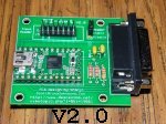
Anyway here's my take on making a working adapter - took schematics into free version of Eagle, made gerber files, sent to Seeed and here it is -
Big THANK You to all the creators/coders that made this possible ..
--
Mozz
(got 0.7ver zip, I think, from some IRC channel
Anyway here's my take on making a working adapter - took schematics into free version of Eagle, made gerber files, sent to Seeed and here it is -
- PCBs
--
Mozz
-
jaffa225man
- DBB Cadet
- Posts: 15
- Joined: Mon Dec 15, 2014 5:32 pm
Re: Reverse Engineering the Force Feedback Pro
That looks great mozgy! Thanks, also, for showing us an easy way to make a pcb without stringing out wires on a protoboard (the way I did). Seeedstudio's "Fusion PCB" looks useful. Services like that can always come in handy.  Being a free software enthusiast, myself, I'd probably try creating and exporting the gerber file from something like GNU electric (if it truly supports gerber I/O), or gEDA's PCB editor.
Re: Reverse Engineering the Force Feedback Pro
There has been talk in the past about the possibility that the Force Feedback Pro which does not have a fan may have problems when using this adapter. I have been thinking about it for a while now and decided to try to get to the bottom of things. Is there actually a problem and if so, what can be done to make the no fan version of the joystick work correctly.
As you should know from past posts, I have been making this adapter for a couple of years now so I figured I had a good pool of information to access for some facts. I sent out a mass email to the last 80 people or so who have bought the adapter I am building. Probably 2/3 of those were purchased for FFP joysticks. I asked for product ID, whether or not it has a fan, and does it function as you expect it to. I've gotten a few responses and had a couple discussions and I'm starting to think that the problem is not related to the joystick. These are the results I have so far:
These joysticks all function as the owner expects them to. 4 of them I never found out if they have a fan or not but I am thinking they don't based on the PID#. It looks to me like MS was using the 3rd grouping of numbers as a serial number and the first digit in the last group to indicate the serial numbers have rolled over 10 million. If that is true, then I see no reason that there would be a fan in later units once they made the decision to remove it, somewhere between 200 and 400 thousand. If anyone has seen a breakdown of how the hardware PIDs are used, please forward it to me.
I have only had one customer that I could not get the adapter working for him. He had a fan version. He sent the adapter back for a refund and i retested the adapter when I received it back and it passed. I don't know what the issue was because he had limits on how he could test (equipment available to him) and we couldn't verify that the stick was actually still functional. At any rate, this would not be related to the "no fan" concerns since he said it was a fan version.
I've made about 150 of these and have only had the 1 unit that was returned for a refund for functionality. I'm thinking that the "issue" with no fan versions of the FFP is just not a reality. I have no doubt that some people had problems getting their sticks to work but I don't think it had anything to do with the stick. It's more likely it was something to do with their build, or a bad cable, or some other problem. It's possible some sticks are more finicky about using a breadboard build. I have had some customers that found they had to connect the adapter to their computer first and connect the joystick last or it would not work correctly. With most it does not matter. Just hook it up and it works. Order doesn't matter.
I can't say that all sticks will work without any problems, but I do think your odds are very good that it will work with the adapter that I am building. One failure out of 150 sales that may or may not have been related to the adapter is still pretty good odds. I don't think we need to be concerned about it.
Scott
As you should know from past posts, I have been making this adapter for a couple of years now so I figured I had a good pool of information to access for some facts. I sent out a mass email to the last 80 people or so who have bought the adapter I am building. Probably 2/3 of those were purchased for FFP joysticks. I asked for product ID, whether or not it has a fan, and does it function as you expect it to. I've gotten a few responses and had a couple discussions and I'm starting to think that the problem is not related to the joystick. These are the results I have so far:
Code: Select all
Product ID: 96755-579-0001360-00000 (fan)
Product ID: 96755-579-0046903-00000 (fan)
Product ID: 96755-579-0228490-00000 (fan)
Product ID: 96755-579-0413474-00000 (no fan)
Product ID: 96755-579-0463576-00000 (no fan)
Product ID: 96755-579-0495052-00000 (fan)  {fan was reported by owner but not sure it's there...}
Product ID: 66883-579-1468063-10000 (no fan)
Product ID: 66883-579-1778595-10000
Product ID: 66883-579-2324971-10000 (no fan)
Product ID: 66883-579-2927825-10000 (no fan)
Product ID: 66883-579-3406152-10000 (no fan)
Product ID: 66883-579-3295252-10000
Product ID: 66883-579-8580241-00000
Product ID: 66883-579-9035425-00000
I have only had one customer that I could not get the adapter working for him. He had a fan version. He sent the adapter back for a refund and i retested the adapter when I received it back and it passed. I don't know what the issue was because he had limits on how he could test (equipment available to him) and we couldn't verify that the stick was actually still functional. At any rate, this would not be related to the "no fan" concerns since he said it was a fan version.
I've made about 150 of these and have only had the 1 unit that was returned for a refund for functionality. I'm thinking that the "issue" with no fan versions of the FFP is just not a reality. I have no doubt that some people had problems getting their sticks to work but I don't think it had anything to do with the stick. It's more likely it was something to do with their build, or a bad cable, or some other problem. It's possible some sticks are more finicky about using a breadboard build. I have had some customers that found they had to connect the adapter to their computer first and connect the joystick last or it would not work correctly. With most it does not matter. Just hook it up and it works. Order doesn't matter.
I can't say that all sticks will work without any problems, but I do think your odds are very good that it will work with the adapter that I am building. One failure out of 150 sales that may or may not have been related to the adapter is still pretty good odds. I don't think we need to be concerned about it.
Scott
=================
More info is on MY SITE.
More info is on MY SITE.
Re: Reverse Engineering the Force Feedback Pro
I have been looking at this site for some time. But after playing both Elite: Dangerous and Star Citizen I really needed my old friend MS FFB pro to be reborn.
I forgot how nice it was, even with the FFB "offline" the stick feels great, I worked on military aircraft and for the money it is still the best around for a fly by wire simulation. The passive auto center itself is a great thing.
So, I finally got a teeny 2.0 and went for it. Using the adapt-ffb-joy hardware instructions.
My first attempt, was lackluster and although the driver was correctly identified, the stick led was blinking and the motors were not engaged. Not all of the buttons work the POV switch is pointing down and the throttle is all over the place.
So I added the, "optional", caps and got the light on solid and the motors are live, but still not quite perfect yet.
Any advice?
Re: Reverse Engineering the Force Feedback Pro
To be honest, you're not going to achieve perfection. There are no profiles, we can't adjust the force levels, it's a pain to switch between different sidewinder models...but we try to get as close as we can.blightcp wrote:So I added the, "optional", caps and got the light on solid and the motors are live, but still not quite perfect yet.
Any advice?
Could you tell us what is not "perfect" about it and what you expect from it? We might have some ideas that can get you closer to what you want. I assume that "the motors are live" means the stick is centering. Are you getting FFB effects in a game? Have you tested with the ForceTest.exe utility? What exactly is it not doing that you feel it should be doing?
=================
More info is on MY SITE.
More info is on MY SITE.
-
jaffa225man
- DBB Cadet
- Posts: 15
- Joined: Mon Dec 15, 2014 5:32 pm
Re: Reverse Engineering the Force Feedback Pro
Blightcp, I'm no expert in the hardware, but I did build it myself from the same instructions you used. Here are my (expected?) results:
When I plug it into power and then connect the USB, I instantly get the power LED on the joystick itself to light, and it stays on until I unplug it from USB or power. It's off completely if I unplug USB, but if I unplug just the power and not the USB, I get a flashing LED on the joystick, possibly as you've described. Interestingly to me, as I wouldn't have tried it without trying to diagnose your issue, without power plugged in, the joystick still functions with all the buttons and controls as normal; it just doesn't work with any force feeback including auto-centering. I have the version with the fan and it, also, doesn't run when not plugged into power. When I plug in the USB I get two to four flashes and then a longer flash on the adapter's LED; it then turns off until I start a program that uses force-feedback (and then it flashes whenever it, presumably, receives force data).
I initially built it with the capacitors because I read about others with issues and figured there was no downside to them. Anyway, my POV shows it's centered, my throttle is steady, and buttons 1-9 (9 being the shift arrow button) all function without my code modification. If you want button 9 to act more like it does on an actual gameport, that's what my modification does.
Scanjo is correct about there not being force strength tuning software for the joystick on this adapter, but I think the default forces are alright and most games support force configuration in-game anyway. If you want the default auto-centering to work, run any force-feedback program or game to start the forces and then exit (i.e. open forcetest.exe, mentioned by scanjo, and enable one force and then close it; auto-centering should now be on).
Your jumpy throttle, stuck POV, and buttons not functioning makes me think dust got inside. It would be nice to test it on a computer with the gameport connector to rule out those sorts of issues.
Good luck!
Re: Reverse Engineering the Force Feedback Pro
Sorry for the slow response, life got in the way.
Thanks for verifying the behavior for me, I will open it up and check contacts and dust.
As for my perfect remark, what I mean is serviceable with all of the major function working properly. As a test engineer and programmer myself I know how hard it is to backwards engineer things.
I don't have another PC with a gameport, all of my PC's are win 7 or 8. Unless, has anyone ever tried using a game port in VMware? That MAY be able to grab the hardware as the main OS is not using it. But that would take some serious time to get a XP setup running.
Once I check for dust, corrosion and cold solder joints I will post an update.
Thanks
Re: Reverse Engineering the Force Feedback Pro
So, I just opened it up and the bottom look good and clean, there is no "fan" just vents to give that impression.
I am even more impressed now that I have opened this up. I did not realize there is a light beam detecting the presence of a hand, And the sophistication of the optical system is impressive, they basically remade a "real" stick.
You can really tell that this was made in the 90's flux all over the place and sharpie test markings causing corrosion. Corrosion on the plated surfaces and leads. If this was a commercial aircraft product I would condemn it. This is one of the reasons that the ROHS production standards were made and implemented in the early 2000's. And one of the reasons why computers are lasting longer than they did before. But I digress.
The top hat control board is the worst of them, It looks like the micro switches are pretty beat up. I will have to look into it and see if replacements can be ordered. The problem is that they are a horizontal switch with a vertical mount, non typical but still used, if I can find them I will post the part info.
Re: Reverse Engineering the Force Feedback Pro
@jaffa225man- Re: button 9 "acting more like it does on an actual gameport", what system are you using for your actual gameport? As I recall, when my system was Win98, the shift button would only work as a shift in two ways:
This is not to say that you're doing anything wrong by implementing shift functionality in the FFB-Vert firmware! All I'm saying is that your implementation seems to me to be not "as it was", but in fact better than it was, if it makes the 8 regular buttons transparently appear to games as if they are 16 buttons, regardless of whether the game understands the concept of a "shift button".
- If the game explicitly recognized it as a shift button. Jane's WWII Fighters does this, as can be seen by examining ww2keys.txt (key and joy mappings control file). Notice the references and entries mentioning "JOY_SHIFT".
- If the user set it up that way using the Microsoft Sidewinder Game Controller profile software, that only works on pre-XP OS'es.
This is not to say that you're doing anything wrong by implementing shift functionality in the FFB-Vert firmware! All I'm saying is that your implementation seems to me to be not "as it was", but in fact better than it was, if it makes the 8 regular buttons transparently appear to games as if they are 16 buttons, regardless of whether the game understands the concept of a "shift button".
Re: Reverse Engineering the Force Feedback Pro
Apologies for the necro-quote...roid wrote:is anyone interested in mechanical joystick hacks?
ie: not so much the circuitboards or software, but the actual shape and mechanical movement of the joystick. Gimball design, springs, motor & button placement/feel, etc.
A guy at my local hackerspace has been experimenting with his own joystick designs. http://openjoystick.com/
And i've been noticing some interesting stuff on thingiverse, albiet it's mostly small console-style thumb sticks. Has any of it been of interest to the topic at hand?
[youtube]GIY6-3KwIS8[/youtube]
One improvement I'd like to make to the FFP would be to replace the gears and sectors with either a cable-drive system, or with gears and sectors having herringbone-cut teeth. The straight-cut teeth MS chose to use give a bit of a rumbly/notchy feel, especially under strong forces, that really shouldn't be there. Helical-cut teeth might work too but could cause wear and tooth-skipping problems due to edge side-thrust loads that don't occur with straight or herringbone teeth.
-
jaffa225man
- DBB Cadet
- Posts: 15
- Joined: Mon Dec 15, 2014 5:32 pm
Re: Reverse Engineering the Force Feedback Pro
Scotophor, thanks for pointing that out. I was under the impression that the shift should be defined as such because of XP's control panel test. When I retested it on a gameport (on windows millennium), I "unloaded" the profile software (which I hadn't tweaked shift-functionality on anyway), and tested a game that apparently doesn't support it: Star Wars Racer. Shift is, indeed, detected immediately as button 10 (I wonder why not 9) without allowing for any combined button presses.
It also occurs to me that, it's not likely any game will implement specific shift functionality for the force feedback pro on any USB adapter because even if we are to use microsoft's USB descriptor for the force feedback pro 2, it didn't include the shift button. I'm not sure my change makes it work with old games that are set up to recognize the force feedback pro's shift. They'd have to be fancy enough to expect more joystick buttons on any generic joystick. It should work with all new games that expect USB HID protocol, though.
Thanks for appreciating it as an improvement (which I didn't realize it was).
Re: Reverse Engineering the Force Feedback Pro
BTW jaffa225man, I don't actually have an Adapt-FFB-Joy yet; I'm on the waiting list for Scanjo's FFB-Vert run #3. How does your modified firmware implement the shift function? IMO, for maximum compatibility it should somehow work both with games that recognize the FFP shift and those that don't. I'm not sure exactly how this could be accomplished, because if button 10 is both internally implemented as a shift, as well as "passed through" as a button 10 press, games that intrinsically recognize button 10 as Shift might then be seeing some kind of a "double-shift", with possibly undesired results. Maybe by altering it so that it is "passed through" as button 9, games that see button 10 as a shift will not recognize it as such?
-
jaffa225man
- DBB Cadet
- Posts: 15
- Joined: Mon Dec 15, 2014 5:32 pm
Re: Reverse Engineering the Force Feedback Pro
Scotophor, most of the games that I have, let me redefine which buttons are used. I have quite a few games, but not too many from the windows 95 era and haven't tested them all for compatibility. Just now, I tried the ones that came with my joystick, on XP (SP3): "Interstate 76", "Star Wars Empires: Battle of Hoth", and "MDK: Mission Laguna Beach". Out of those, only "Star Wars Empires" seems to initiate the force feedback but it has z-buffer rendering problems (even with dxwnd). They all let me define the buttons, though. I don't have the game you mentioned, with definite shift button knowledge. I do have "Jane's USNF '97" but don't see a text file like you mentioned. I did only look at the disc's contents without installation or extraction, however. I know the buttons work in "Star Wars Racer" and believe they also do in "Descent 3" (and should in "DXX-Rebirth" too) and "Star Wars Rogue Squadron 3D"; I'll have to test them again to refresh my memory.
The way I programmed it, the shift button isn't ever pressed by itself. To get button 9, you have to push shift at the same time as button 1. I figured that if I made it a button by itself, it was probable that it would conflict with other scenarios. Since the really old games seem to need some form of emulation on recent OS's anyway, I think emulating 16 buttons in the hardware is a necessary evil, as emulation software will probably mask away the true USB hardware from the software.
The way I programmed it, the shift button isn't ever pressed by itself. To get button 9, you have to push shift at the same time as button 1. I figured that if I made it a button by itself, it was probable that it would conflict with other scenarios. Since the really old games seem to need some form of emulation on recent OS's anyway, I think emulating 16 buttons in the hardware is a necessary evil, as emulation software will probably mask away the true USB hardware from the software.
Re: Reverse Engineering the Force Feedback Pro
So, if I understand that correctly, with your shift-modified firmware, pressing shift alone gives no output, but pressing shift + any button 1-8 gives output identified as a button in the range of 9-16? It seems to me that if there's any game hard-coded to recognize button 10 as Shift, that would cause a problem with shift + button 2... the game would see it as Shift + nothing, and therefore do nothing. But since that's only one button, it could be an acceptable compromise. There probably isn't any game like that anyway, especially since the adapter doesn't identify itself the same as an FFP does. An alternate method would be to offset the numbering of the shifted buttons by two, so that 1-8 = 1-8, but shift + 1-8 = 11-18. Buttons 9 and 10 are skipped. I think testing is in order... I'll see how it works when my adapter gets here.
A potential problem I see is that Jane's WWII Fighters does recognize the "Shift" function, but does not appear to recognize regular button numbers higher than 8. So, I'd have to flash the regular firmware to play it with full functionality, then flash your firmware to play other games with the benefit of Shift (assuming they can recognize more than 8 buttons but not Shift, or button combinations). A workaround for this issue would be to use something like AHK to remap buttons higher than 8 to keystrokes, since WWIIF is designed around keystrokes more than buttons anyway.
A potential problem I see is that Jane's WWII Fighters does recognize the "Shift" function, but does not appear to recognize regular button numbers higher than 8. So, I'd have to flash the regular firmware to play it with full functionality, then flash your firmware to play other games with the benefit of Shift (assuming they can recognize more than 8 buttons but not Shift, or button combinations). A workaround for this issue would be to use something like AHK to remap buttons higher than 8 to keystrokes, since WWIIF is designed around keystrokes more than buttons anyway.
-
jaffa225man
- DBB Cadet
- Posts: 15
- Joined: Mon Dec 15, 2014 5:32 pm
Re: Reverse Engineering the Force Feedback Pro
You understand perfectly. I wish I could program it as a separate button (10) and define others above 18 (therefore gaining one button, the shift alone), but I don't really know the code that well. You see, the buttons were already defined, and I just took that to mean they should be working and implemented them. I know very little about how there were 18 to choose from. That probably would be a LUFA USB descriptor issue and would also probably need bits added to the variable that reports status. As you can see, it's probably not a simple undertaking for someone who's just beginning with avr programming, as I am. It's pretty simple to reflash the firmware, but I hope your tests prove that unnecessary because after too many overwrites the atmega will need replacement.
Re: Reverse Engineering the Force Feedback Pro
Hi all,
I dug out my Sidewinder FFB from my parent's house this last weekend, after being in a closet since around 1999. Googling around led me to the google-code site, the github and this forum.
I was planning to do a headtracking project, before I dug this joystick out, so I already have a Teensy2.0 and a couple of ProMicros, and motion sensors on the way. Now, I think I'll do the stick first before anything else.
On the joystick itself, the power brick is gone and the barrel connector has broken off. In place of the barrel jack, two wires are soldered on and ends in male pin headers. The gameport cable is slimy and sticky, so I cut off the gameport cable. I've already broken out some wires from the motherboard header to a breadboard, following the pin assignments on the wiki. I'm still in the process of wiring up the rest, but I have a few question before I plug this in.
Question 1: I saw a google code site, and a github repo https://github.com/tloimu/adapt-ffb-joy. Am I correct to assume that the github repo is current? Is that the correct github site?
Question 2: Can I get this working without the 12v power, at least initially? I plan on getting the sensors/buttons working first, before the FFB. However, if the code or the board itself requires the 12v parts to work, then I'll have to improvise a way to get 12v from the PC sooner than later.
Question 3: The shield wire from the motherboard should be connected to ground?
Question 4: Since the barrel jack is gone, and I don't trust the color coding of the soldered-on wires. I'd like to ask for confirmation on which one is ground and which is 12v. Here is a picture of the joystick's board, as viewed from the bottom of the stick. This is the backside of the board, the optical sensor is on the other side. Right now the black wire is soldered to the upper terminal in the picture. If someone could confirm that black is ground, or if it's the other way around.

Question 5: I substituted the 2.2KOhm resistors with a pair of 2KOhm + 200Ohm resistors in series since I couldn't find the exact part. Would this work?
Question 6: I've finished wiring up the connections to the Teensy (including the optional capacitors, minus the optional pots). I uploaded the adaptffbjoy-r54.hex file from the google code site to the Teensy. When I plug in the Teensy to USB, I get a rapidly blinking light on the teensy itself, and a slow blink on the joystick. (note: I still don't have 12v power on the stick) At this point, nothing is being detected on the PC. When I press the Teensy rest button, the teensy led stops flashing, the joystick led keeps flashing the same, a USB HID input device is detected, but no joysticks show up. Is this the expected behavior (given that I haven't connected 12v yet)?
I'm more of a programmer by trade than an electronics guy. I know a capacitor from a resistor but that's about it. I'm comfortable handling a soldering iron though, as long as part lists & instructions are available.
thanks in advance everyone
I dug out my Sidewinder FFB from my parent's house this last weekend, after being in a closet since around 1999. Googling around led me to the google-code site, the github and this forum.
I was planning to do a headtracking project, before I dug this joystick out, so I already have a Teensy2.0 and a couple of ProMicros, and motion sensors on the way. Now, I think I'll do the stick first before anything else.
On the joystick itself, the power brick is gone and the barrel connector has broken off. In place of the barrel jack, two wires are soldered on and ends in male pin headers. The gameport cable is slimy and sticky, so I cut off the gameport cable. I've already broken out some wires from the motherboard header to a breadboard, following the pin assignments on the wiki. I'm still in the process of wiring up the rest, but I have a few question before I plug this in.
Question 1: I saw a google code site, and a github repo https://github.com/tloimu/adapt-ffb-joy. Am I correct to assume that the github repo is current? Is that the correct github site?
Question 2: Can I get this working without the 12v power, at least initially? I plan on getting the sensors/buttons working first, before the FFB. However, if the code or the board itself requires the 12v parts to work, then I'll have to improvise a way to get 12v from the PC sooner than later.
Question 3: The shield wire from the motherboard should be connected to ground?
Question 4: Since the barrel jack is gone, and I don't trust the color coding of the soldered-on wires. I'd like to ask for confirmation on which one is ground and which is 12v. Here is a picture of the joystick's board, as viewed from the bottom of the stick. This is the backside of the board, the optical sensor is on the other side. Right now the black wire is soldered to the upper terminal in the picture. If someone could confirm that black is ground, or if it's the other way around.
Question 5: I substituted the 2.2KOhm resistors with a pair of 2KOhm + 200Ohm resistors in series since I couldn't find the exact part. Would this work?
Question 6: I've finished wiring up the connections to the Teensy (including the optional capacitors, minus the optional pots). I uploaded the adaptffbjoy-r54.hex file from the google code site to the Teensy. When I plug in the Teensy to USB, I get a rapidly blinking light on the teensy itself, and a slow blink on the joystick. (note: I still don't have 12v power on the stick) At this point, nothing is being detected on the PC. When I press the Teensy rest button, the teensy led stops flashing, the joystick led keeps flashing the same, a USB HID input device is detected, but no joysticks show up. Is this the expected behavior (given that I haven't connected 12v yet)?
I'm more of a programmer by trade than an electronics guy. I know a capacitor from a resistor but that's about it. I'm comfortable handling a soldering iron though, as long as part lists & instructions are available.
thanks in advance everyone
Re: Reverse Engineering the Force Feedback Pro
I'll just address the questions I think I can answer...
Funny, my SW FFB Pro is hacked at the power jack too. I remember that when I found mine in a thrift store, it didn't have its power brick either, naturally. I picked up a 12VDC, 1.5A brick at Radio Shack, the ones where you get any one of their available DC plugs free with it. I guess they didn't have the style that the FFB Pro takes at that time (I later found out that they did normally carry the correct style, so it was probably just out of stock) so I got a different plug style and swapped out the jack in the stick to match it, which required drilling a fairly big hole in the circuit board to accommodate the new jack's different terminal arrangement. I've never had a problem with it since doing the mod and getting it working.
----------
BTW, has anyone heard from Scott "Scanjo" Johnson lately? Even though his FFB-Vert Orders page claims to be updated every so often, I haven't noticed any major changes other than perhaps new names added to the bottom since October. I've been on the list a little way below where the "in progress" animated icons are for about 8 months. Regarding the statement at the bottom of the page, "Just a reminder...I will be building slower in the warmer months due to increased outdoor activities", at least where I am it's gone from warm to cold and back to warm again already, with no apparent progress. I could understand if he wants to discontinue his building service, but IMO he should let us know if that's the case.
I just tested my SW FF Pro under WinXP on a machine with a real gameport. Without 12VDC power, and with the green LED on the stick base blinking, it shows up under Control Panel > Game Controllers as "OK" and all inputs seem to work normally. So without 12VDC, apparently all you lose is the FFB.r8dhex wrote:Question 2: Can I get this working without the 12v power, at least initially? I plan on getting the sensors/buttons working first, before the FFB. However, if the code or the board itself requires the 12v parts to work, then I'll have to improvise a way to get 12v from the PC sooner than later.
From your photo and description it looks like you're correct, black (top/left) is - and white (bottom/right) is +.r8dhex wrote:Question 4: Since the barrel jack is gone, and I don't trust the color coding of the soldered-on wires. I'd like to ask for confirmation on which one is ground and which is 12v. Here is a picture of the joystick's board, as viewed from the bottom of the stick. This is the backside of the board, the optical sensor is on the other side. Right now the black wire is soldered to the upper terminal in the picture. If someone could confirm that black is ground, or if it's the other way around.
Funny, my SW FFB Pro is hacked at the power jack too. I remember that when I found mine in a thrift store, it didn't have its power brick either, naturally. I picked up a 12VDC, 1.5A brick at Radio Shack, the ones where you get any one of their available DC plugs free with it. I guess they didn't have the style that the FFB Pro takes at that time (I later found out that they did normally carry the correct style, so it was probably just out of stock) so I got a different plug style and swapped out the jack in the stick to match it, which required drilling a fairly big hole in the circuit board to accommodate the new jack's different terminal arrangement. I've never had a problem with it since doing the mod and getting it working.
That will work fine. It would probably work just as well with only the 2.0 k resistors too.r8dhex wrote:Question 5: I substituted the 2.2KOhm resistors with a pair of 2KOhm + 200Ohm resistors in series since I couldn't find the exact part. Would this work?
----------
BTW, has anyone heard from Scott "Scanjo" Johnson lately? Even though his FFB-Vert Orders page claims to be updated every so often, I haven't noticed any major changes other than perhaps new names added to the bottom since October. I've been on the list a little way below where the "in progress" animated icons are for about 8 months. Regarding the statement at the bottom of the page, "Just a reminder...I will be building slower in the warmer months due to increased outdoor activities", at least where I am it's gone from warm to cold and back to warm again already, with no apparent progress. I could understand if he wants to discontinue his building service, but IMO he should let us know if that's the case.
Re: Reverse Engineering the Force Feedback Pro
Good to know. However, I guess I should re-check my wiring to see if I crossed something. Does your Teensy blink rapidly during normal use? Mine blinks quickly, but I don't know if that's normal, or a sign that something is off.Scotophor wrote:I'll just address the questions I think I can answer...
I just tested mine under WinXP on a machine with a real gameport. Without 12VDC power, and with the green LED on the stick base blinking, it shows up under Control Panel > Game Controllers as "OK" and all inputs seem to work normally. So without 12VDC, apparently all you lose is the FFB.r8dhex wrote:Question 2: Can I get this working without the 12v power, at least initially? I plan on getting the sensors/buttons working first, before the FFB. However, if the code or the board itself requires the 12v parts to work, then I'll have to improvise a way to get 12v from the PC sooner than later.
Thanks for confirming this. Yeah, mine broke off too. I think the jack was prone to breaking off if not careful, and the powerbrick plug wasn't a very common type, at least at that time.Scotophor wrote:From your photo and description it looks like you're correct, black (top/left) is - and white (bottom/right) is +.r8dhex wrote:Question 4: Since the barrel jack is gone, and I don't trust the color coding of the soldered-on wires. I'd like to ask for confirmation on which one is ground and which is 12v. Here is a picture of the joystick's board, as viewed from the bottom of the stick. This is the backside of the board, the optical sensor is on the other side. Right now the black wire is soldered to the upper terminal in the picture. If someone could confirm that black is ground, or if it's the other way around.
Funny, my SW FFB Pro is hacked at the power jack too. I remember that when I found mine in a thrift store, it didn't have its power brick either, naturally. I picked up a 12VDC, 1.5A brick at Radio Shack, the ones where you get any one of their available DC plugs free with it. I guess they didn't have the style that the FFB Pro takes at that time (I later found out that they did normally carry the correct style, so it was probably just out of stock) so I got a different style and swapped out the jack in the stick, which required drilling a fairly big hole in the circuit board to accommodate the new jack's different terminal arrangement. I've never had a problem with it since doing the mod and getting it working.
Yeah, I thought in theory it should work, but given that my setup isn't working yet, I thought I'd ask.Scotophor wrote:That will work fine. It would probably work just as well with only the 2.0 k resistors too.r8dhex wrote:Question 5: I substituted the 2.2KOhm resistors with a pair of 2KOhm + 200Ohm resistors in series since I couldn't find the exact part. Would this work?
Update:I rechecked my wiring and realized that I forgot to wire up most of the pins. The wires from the stick were on the other side of the breadboard, and i forgot to jump the gap. Noob mistake, will get to it this weekend
Re: Reverse Engineering the Force Feedback Pro
I don't have a Teensy yet. I'm still waiting for my FFB-Vert from Scanjo; he hasn't even asked me for payment yet, and apparently some others that are currently "in progress" have to be completed before work on mine will begin.r8dhex wrote:Does your Teensy blink rapidly during normal use? Mine blinks quickly, but I don't know if that's normal, or a sign that something is off.
Re: Reverse Engineering the Force Feedback Pro
The light on my Teensy only blinks when force feedback commands are being sent to the stick. I use a program called Forcetest to send test commands (FYI - you have to be gripping the stick for force feedback to work - there is a proximity sensor in the handle).r8dhex wrote:Does your Teensy blink rapidly during normal use? Mine blinks quickly, but I don't know if that's normal, or a sign that something is off.
Mine works with the teensy without power. When I need a power brick I go to a thrift store and look through the bin of power supplies most thrift stores have. Find a 12v power supply that is at least 1.3 amps and wire it to the joystick. Might want to bring a magnifying glass if your vision isn't so good, the writing is very small on some of those power bricks.Can I get this working without the 12v power, at least initially?
Edit: If the stick you have is the version that has a cooling fan, you might want to wire in a power switch as well.
Re: Reverse Engineering the Force Feedback Pro
Thanks for the replies. Yeah I found out that I forgot to place enough wires on my breadboard. I won't have time to get back to it until this weekend, but I checked the code, and it does seem that rapid blinking is because the Teensy couldn't get a connection to the joystick during initialization.
Re: Reverse Engineering the Force Feedback Pro
I managed to find some time this evening to redo my wiring. I had to open up the joystick again and replace the wires I used last time. Some of the wires had snapped, I guess I cut a bit too hard when I was stripping them.
This time, I used a Cat5E cable to wire up 8 of the 10 pins, the color coding helped a bit since I didn't have enough different colored wires. VCC and GND used another 2 wires.
Eventually, I managed to put it back together and wire everything up to the Teensy. This time it works and is detected as a joystick. Thanks to Grendel, cal and all the rest of the people who contributed to rev. engineering the SW sticks
FFB was easy enough to test. I found a 12v 1.5A adapter from an external HD and taped it to the exposed 12v wires from my stick. FFB works using the tools found in github wiki. I'll need to solder it to a proper barrel connector eventually. Also, the fan is a bit noisy, maybe grease or replace it.
All the axes work, stable when FFB off. The buttons mostly work, the trigger needed to be pressed hard to register, buttons 2,3,4 don't always register. I managed to open up the grip (after a few tries, breaking the plastic clips in the process), replaced the 2,3 & 4 switches with new tact-switches. It also took a bit of filing down the new switches which were a tad taller than the old ones. The trigger switch is different, and I wasn't able to replace it yet.
I noticed that axes have some jittering with FFB on. It's noticeable when you alternately cover/uncover the IR sensor on the grip. Could this be a wiring issue, interference perhaps?
Also, not sure if FFB axes direction is reversed. For example, when I use FFConst.exe, clicking on the upper part of the window pushes the stick downwards, left part pushes to the right.
This time, I used a Cat5E cable to wire up 8 of the 10 pins, the color coding helped a bit since I didn't have enough different colored wires. VCC and GND used another 2 wires.
Eventually, I managed to put it back together and wire everything up to the Teensy. This time it works and is detected as a joystick.
FFB was easy enough to test. I found a 12v 1.5A adapter from an external HD and taped it to the exposed 12v wires from my stick. FFB works using the tools found in github wiki. I'll need to solder it to a proper barrel connector eventually. Also, the fan is a bit noisy, maybe grease or replace it.
All the axes work, stable when FFB off. The buttons mostly work, the trigger needed to be pressed hard to register, buttons 2,3,4 don't always register. I managed to open up the grip (after a few tries, breaking the plastic clips in the process), replaced the 2,3 & 4 switches with new tact-switches. It also took a bit of filing down the new switches which were a tad taller than the old ones. The trigger switch is different, and I wasn't able to replace it yet.
I noticed that axes have some jittering with FFB on. It's noticeable when you alternately cover/uncover the IR sensor on the grip. Could this be a wiring issue, interference perhaps?
Also, not sure if FFB axes direction is reversed. For example, when I use FFConst.exe, clicking on the upper part of the window pushes the stick downwards, left part pushes to the right.
Re: Reverse Engineering the Force Feedback Pro
You might try some contact cleaner on the trigger switch.r8dhex wrote:The trigger switch is different, and I wasn't able to replace it yet.
...
I noticed that axes have some jittering with FFB on. It's noticeable when you alternately cover/uncover the IR sensor on the grip. Could this be a wiring issue, interference perhaps?
By jittering, you you mean that the stick waggles from side to side trying to center itself? Mine does this too sometimes, mostly during tests - less so in games. Depends on your spring center adjustments in your test software and can get worse if you have effects like friction, damping, and/or grooves enabled. I know this stick uses optical sensors for the axes - if those are dirty perhaps cleaning them or just blowing them out with some canned air might help...
Re: Reverse Engineering the Force Feedback Pro
Actually, the trigger finally died, after I put the grip back. No amount of pressure will work. I found the part numbers for those switches and I'm trying to order them (cheaply, intl shipping costs more than the parts).osterac wrote:You might try some contact cleaner on the trigger switch.r8dhex wrote:The trigger switch is different, and I wasn't able to replace it yet.
...
I noticed that axes have some jittering with FFB on. It's noticeable when you alternately cover/uncover the IR sensor on the grip. Could this be a wiring issue, interference perhaps?
By jittering, you you mean that the stick waggles from side to side trying to center itself? Mine does this too sometimes, mostly during tests - less so in games. Depends on your spring center adjustments in your test software and can get worse if you have effects like friction, damping, and/or grooves enabled. I know this stick uses optical sensors for the axes - if those are dirty perhaps cleaning them or just blowing them out with some canned air might help...
By jittering, I don't mean the shaking from FFB. Even when completely centered, holding the stick steady, no forces. There seems to be noise on all the axes, including throttle and twist, when I cover the photosensor. Take my fingers off the photosensor, and everything quiets down. This happens even on the trunk version I compiled.
Re: Reverse Engineering the Force Feedback Pro
When I say the axes use optical sensors I don't mean the one in the handle that senses whether you are gripping the stick. Inside the joystick there is a camera that determines what position the stick and the throttle are in. This video illustrates it quite well:r8dhex wrote:By jittering, I don't mean the shaking from FFB. Even when completely centered, holding the stick steady, no forces. There seems to be noise on all the axes, including throttle and twist, when I cover the photosensor. Take my fingers off the photosensor, and everything quiets down. This happens even on the trunk version I compiled.
https://www.youtube.com/watch?v=IvXyDwlAN8k
Maybe cleaning the lens on that camera or cleaning the tracker LEDs might help?